Week 03: Computer-controlled Cutting

What does Computer-controlled Cutting mean?
 We learned that Computer-Aided Manufacturing (CAM) means the process of operating a machine. It involves the processes that control automated machines and processes in the background. We talked about the difference between additive and subtractive manufacturing. Laser cutting and vinyl cutting are subtractive processes, where we cut something out. Laser cutting is a faster process compared to CNC.
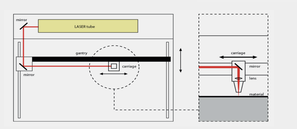
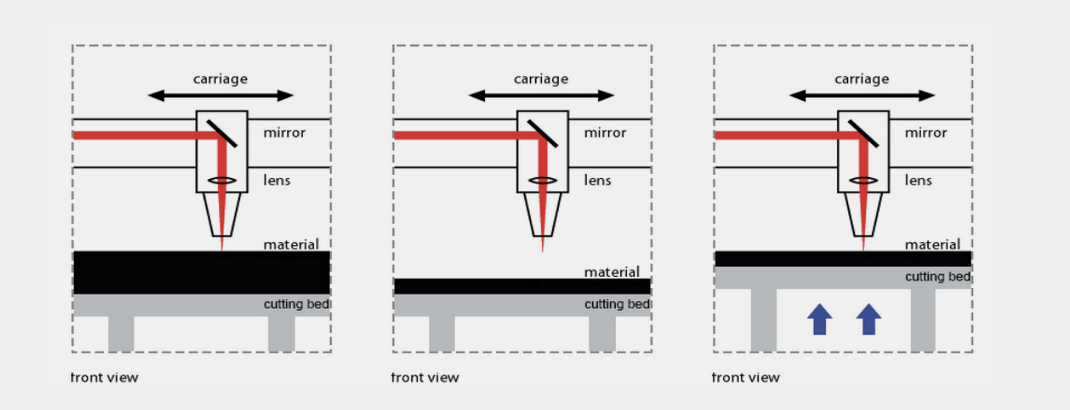 We discussed how the laser works. Inside a laser, there are different mirrors that reflect the light and focus it at the end. To cut a piece, it is very important that the laser meets the material at the right position. So, it's always necessary to focus the lens. To focus the lens, it's necessary to move the bed around. The material has to be as flat as possible. It's forbidden to use reflective materials because the lens will be damaged of the refleciton. It's not possible to cut metal with a laser cutter. There are some parameters that you have to change depending on the cut (fine cut or rough cut) and on the material: Power, Speed, Frequency
There are three options for how you can cut: Engravig, Marking, Cutting. To make different cuts consecutively, it's necessary to put the lines in different colors: black, red, blue. To save material, it's always recommended to make a nesting. There are several options for what you can use laser cutting for (T-shirt printing, Origami etc.)
Group assignment
On this page, you will find all the information regarding to our group assignment.
Parametric Design and Laser Cutting
Fusion 360
 I was eagerly anticipating this week, as I haven't had much experience with laser cutting before. Also I hadn't even heard of parametric design. When I tried it for the first time in class with Fusion, it felt a bit like magic and was realy cool.
For my weekly project, I had the idea to create a parametric and flexible dollhouse, as I'm interested in working with kids in the future. However, creating my first parametric design in Fusion turned out to be more stressful than I had anticipated. I encountered many challenges, as things often didn't work out the way I wanted them to, leading me to create numerous relationship and construction lines. This tutorial helped me a lot. After several hours and with the help of a classmate, it finally has worked, and I was very relieved.
 Just like last week, I started with a sketch again. I selected the "Create Sketch" option and chose a plane to create the sketch on. I first created a square.
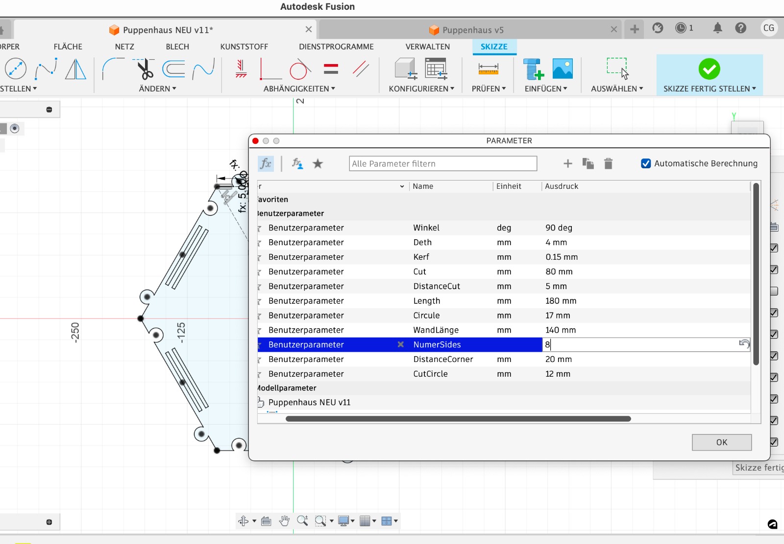
 To work with parameters, these must first be defined. So, I selected the option Modify > Change Parameters. Then, I entered the following parameters:
- Deth (Depth): 4 mm
- Kerf: 0.15 mm
- Cut: 80 mm
- DistanceCut: 5 mm
- Length: 180 mm
- Circle: 17 mm
- WandLänge (Wall Length): 140 mm
- NumerSides (Number of Sides): 4
- DistanceCorner: 20 mm
- CutCircle: 12 mm
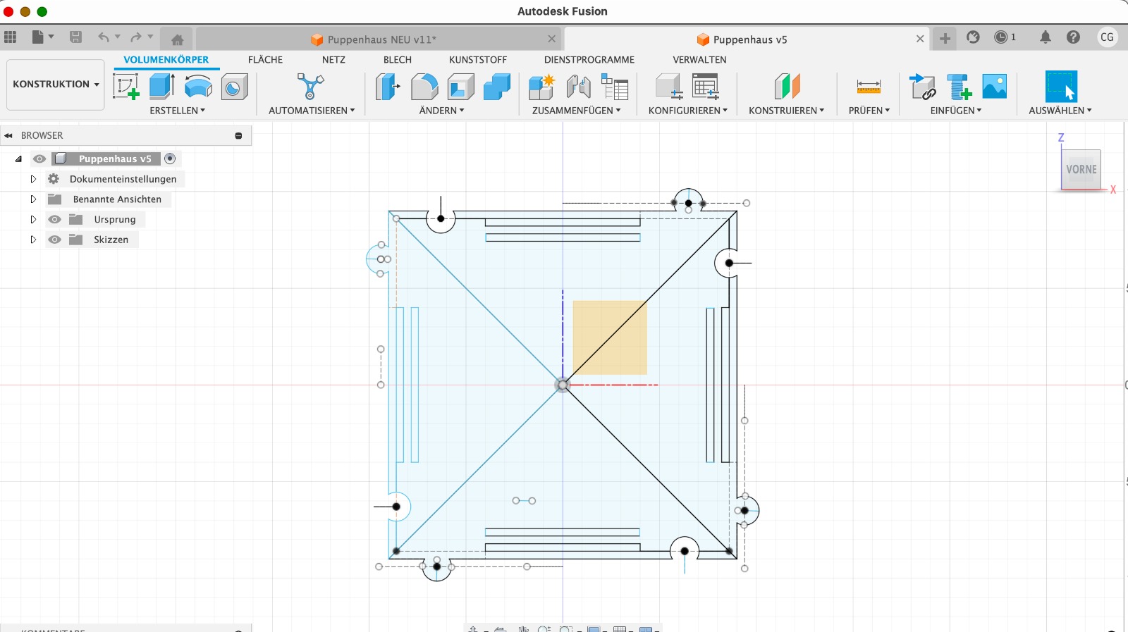
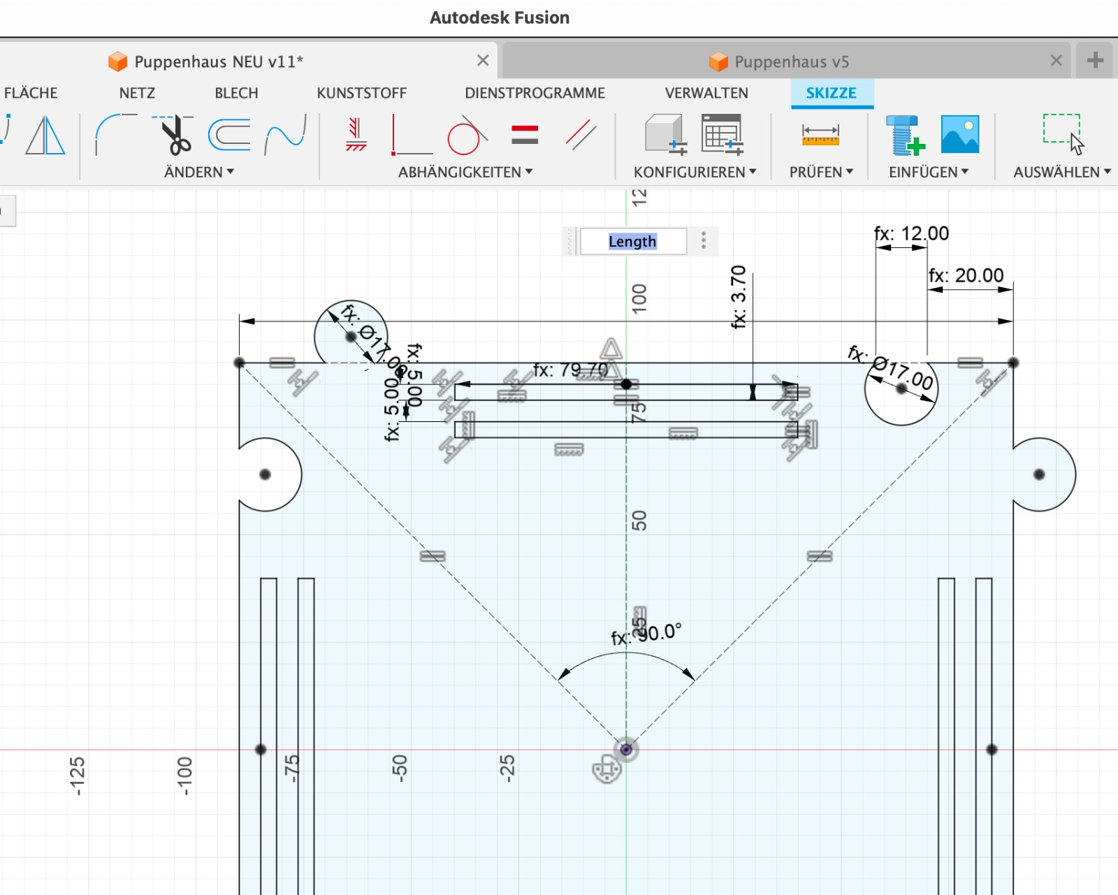 Now I could work with the specified parameters. This works in such a way that when individual lengths or other parameters are determined, no fixed numbers are entered, but rather the names of the parameters (e.g., Length). The advantage is that we can quickly change the design when we replace individual elements.
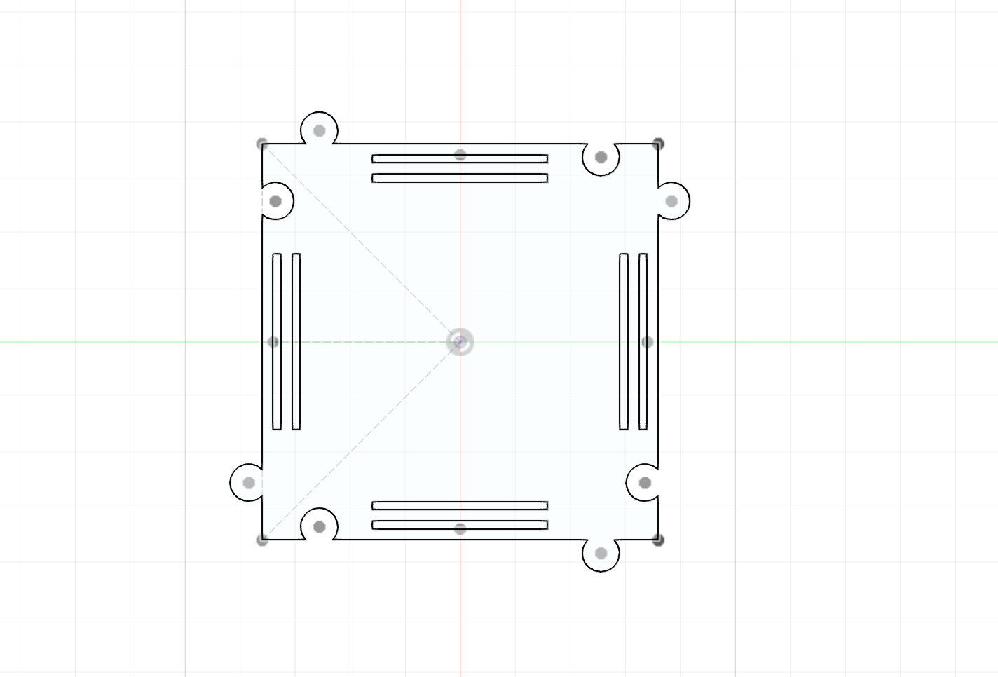
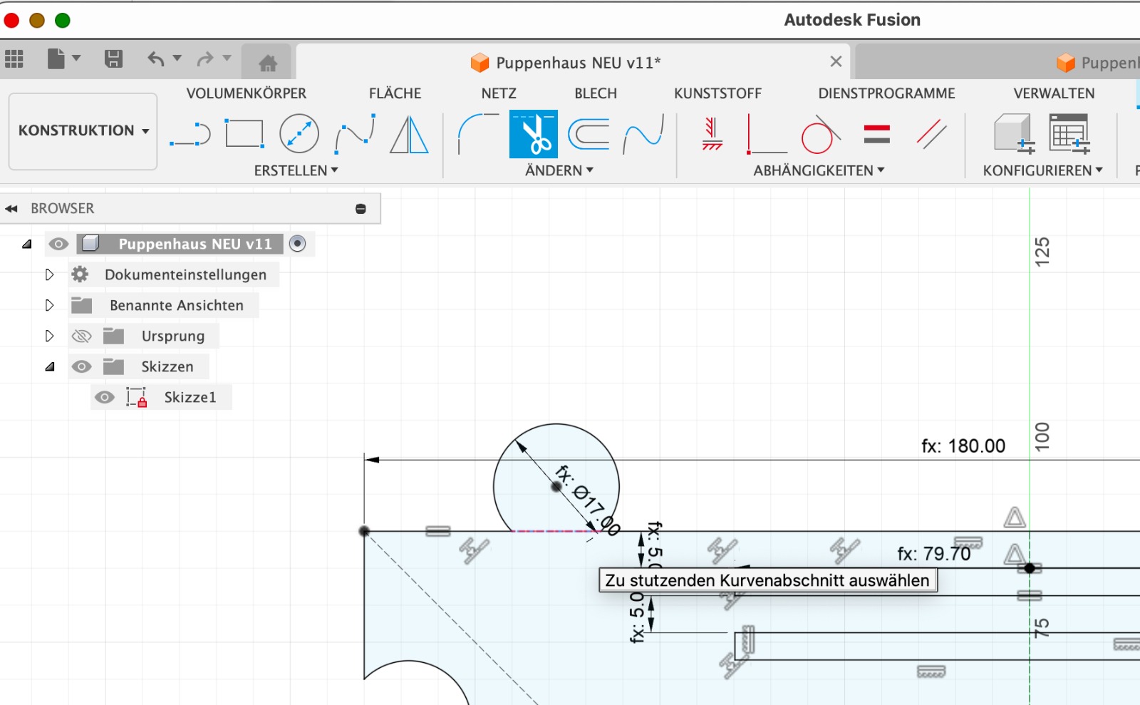 Than I added circles. I placed the center of the circle exactly on the outer line. To properly integrate the circle into the sketch, I used the option Modify > Trim. Depending on which line I trimmed, the circle was integrated outward or inward. The circles serve the purpose of allowing the individual elements to be connected later. The slots on the sides allow the side walls to be inserted into the floor and ceiling.
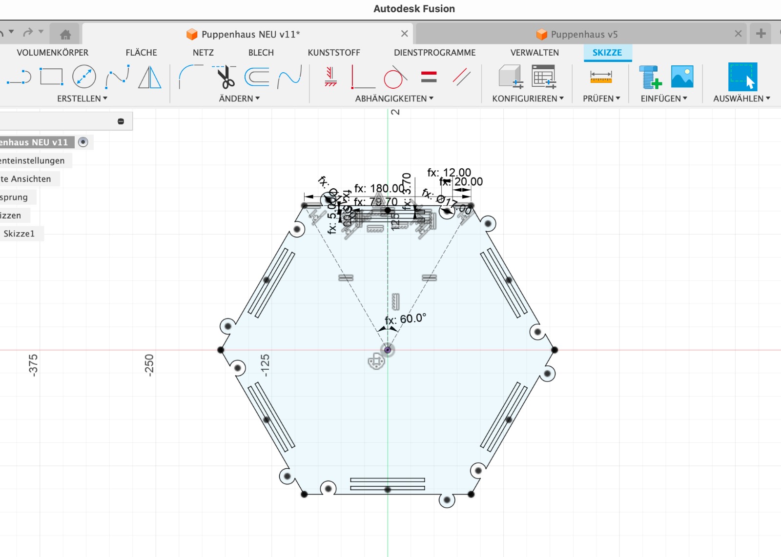
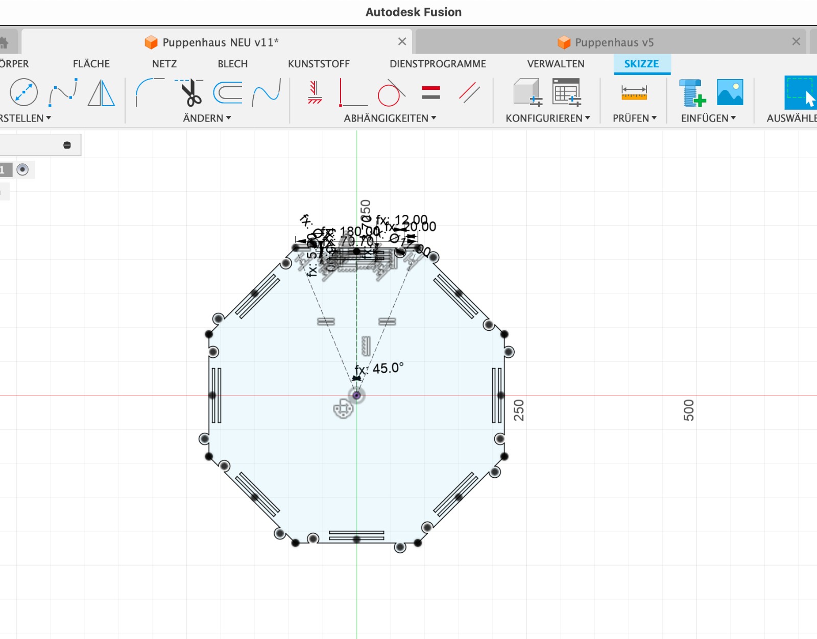
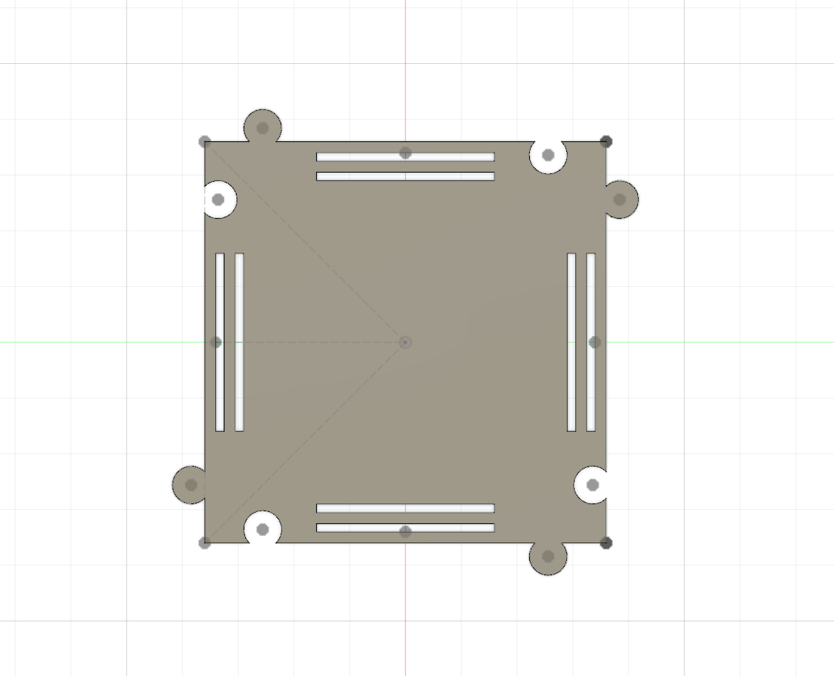
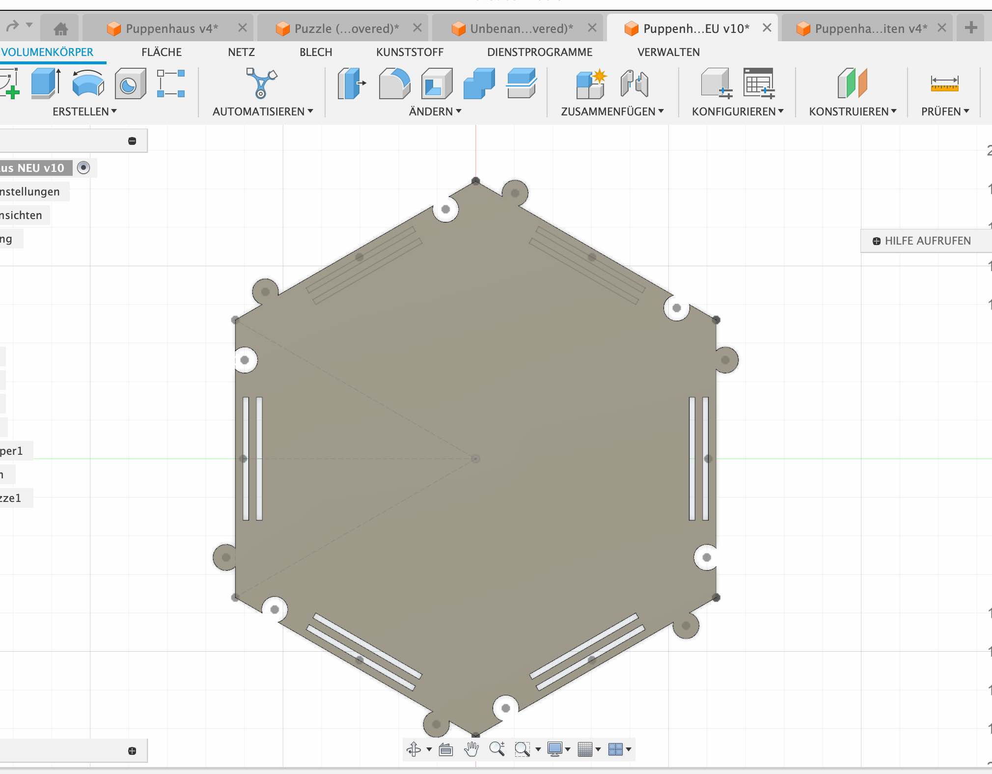
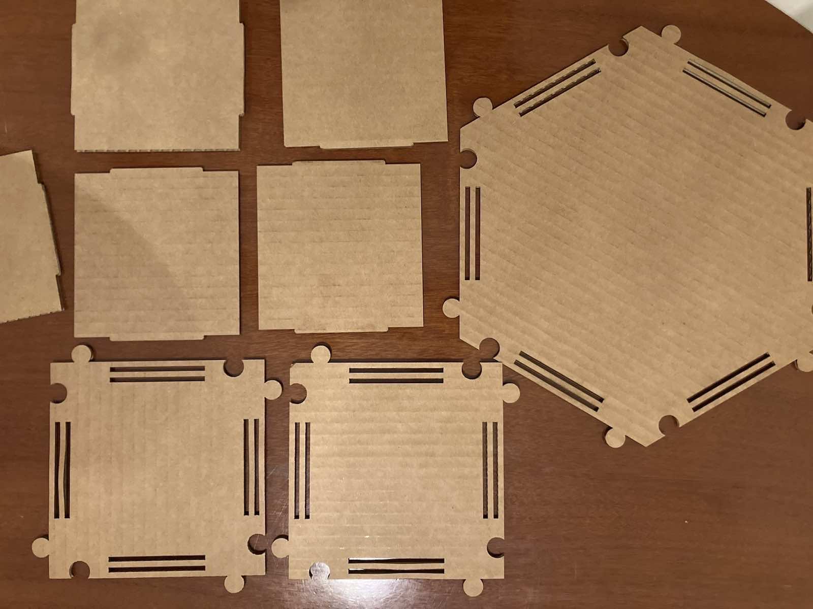
 Working parametrically not only helps to change the overall size of the object but is also a great tool for changing the design by altering the number of sides. The following images show how the design changes when the number of sides is changed from 4 to 6 to 8.
And these were the two final objects which I wanted to cut with the laser cutter.
Rhino
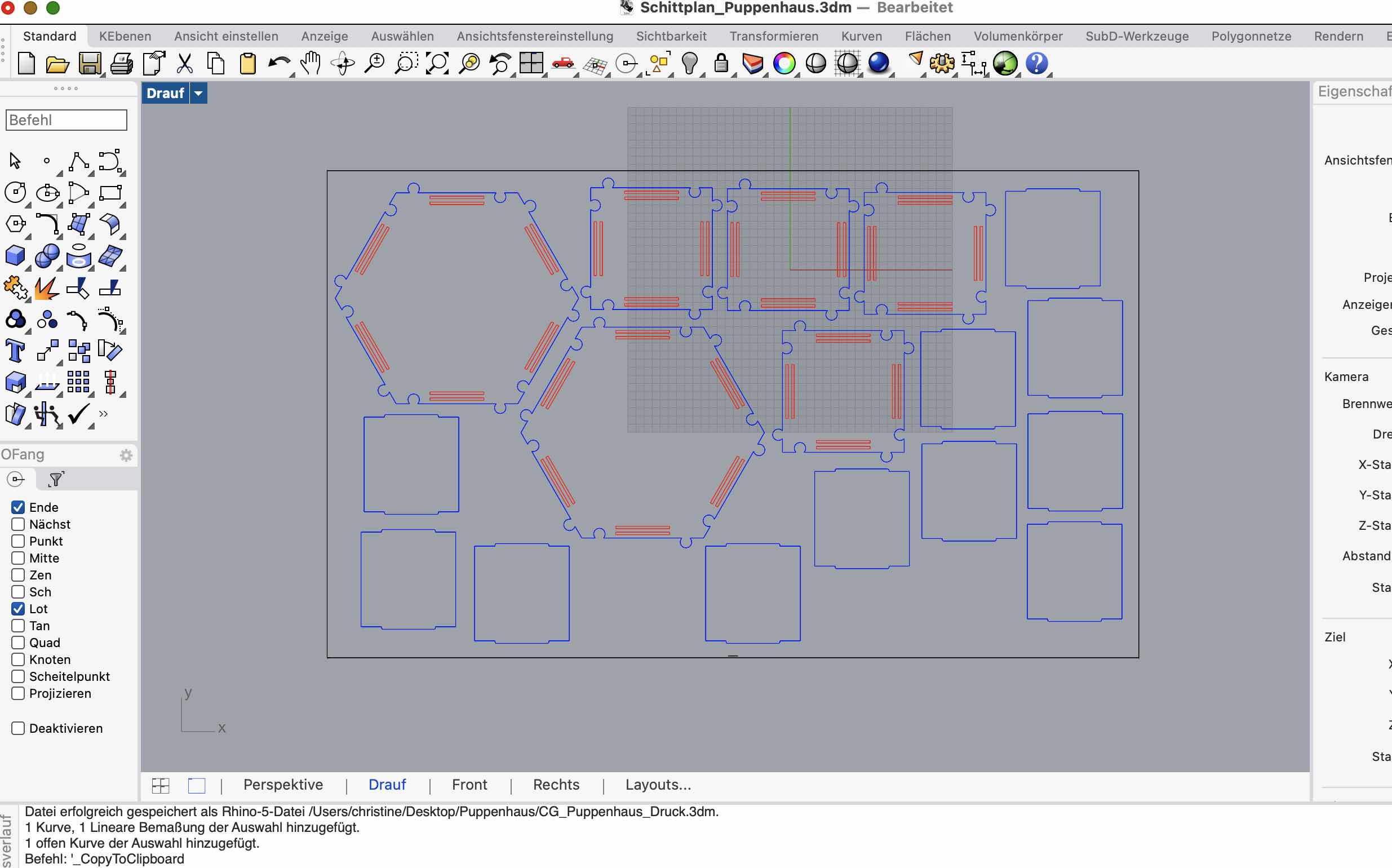 Having never worked with Rhino before, setting up the construction in Rhino was also challenging for me. However, I had to do it because all the machines at FabLab Barcelona operate with Rhino.I needed assistance again, and finally, my cutting sheet was finished, and I could proceed with my first cut.
There were actually only a few commands that I used. After importing, I had to change the size. It is often the case that Rhino does not import the correct size. For this, you can use the Scale command. We enter Scale and select a starting point and an endpoint of a line. Then we specify what length the line should have. If we have previously selected all the objects in the design, all objects will now be scaled proportionally.
An important step is also the grouping of objects. This ensures that we can easily move the objects by, for example, grabbing just one line. The corresponding command is group.
It is also important to prepare the colors accordingly. The laser cutter performs different steps for different colors. Red means Cut and blue means Engrave. Therefore, I adjusted the colors.
Finally, we should place the objects in such a way that we maximize the use of space and minimize waste. I saved the file in the IAAC cloud and could go to the laser cutter.
Laser Cut
I jused the Laser Cutter Trotec Speedy 400.
First, I placed the laser to my starting point. Then, I closed the lid and turned the air compression on. Next, I opened the file on the local computer by downloading it from Fabcloud and opening it in Rhino. I navigated to File > Print, which opened the "Rayjet Manager. I imported the file to the working area, set the material thickness and other settings, and double-checked the air extraction/compression and settings.
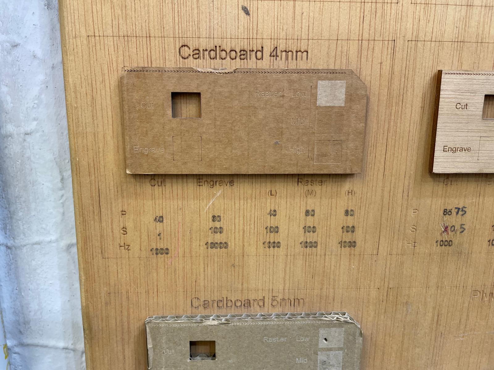
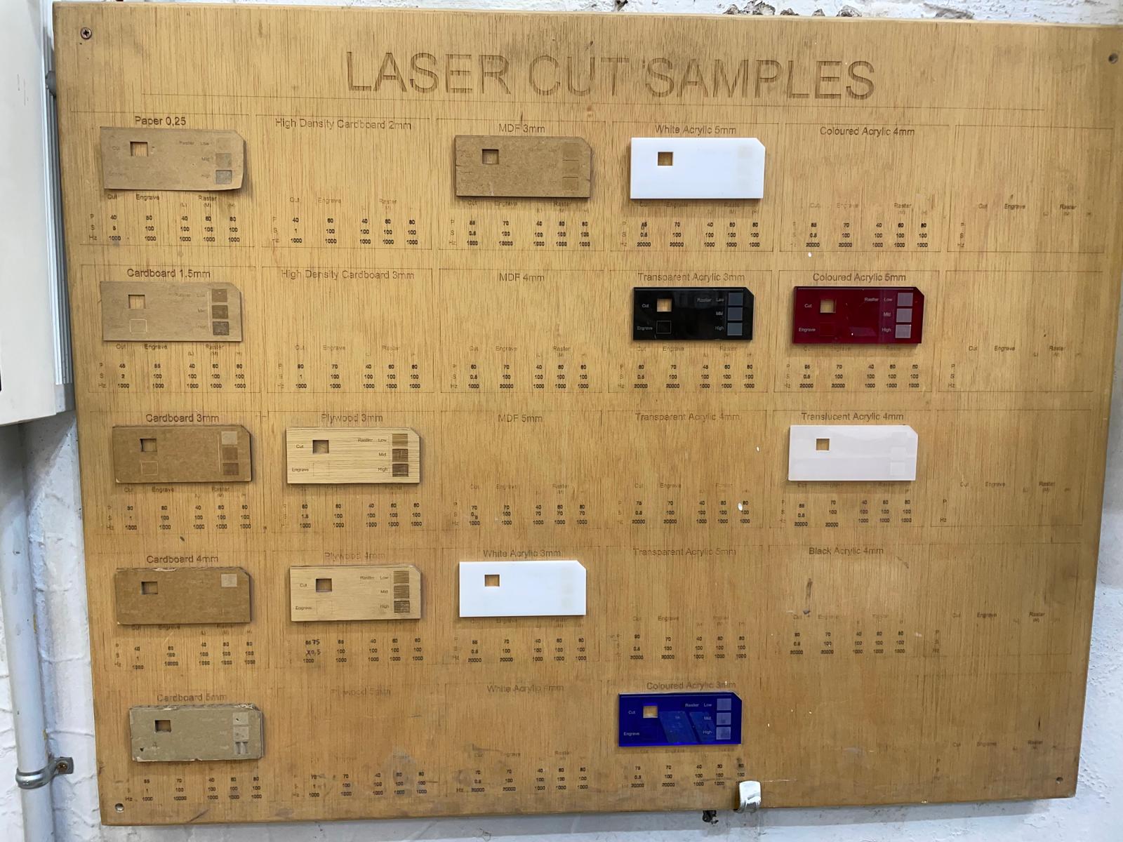 To set the cut correctly, it is important to select the right cutting parameters. These vary from material to material and from machine to machine. And you can finde them for all machines in the lab. Even though there are recommendations for each material, it is always advisable to perform a test. I have selected the parameters for 4mm cardboard: Power: 40, Speed: 1, Hz: 1000. These are the parameters for a cut. If I wanted to do an engraving, I would need different parameters. If the cut doesn't go all the way through, the settings can be slightly adjusted, e.g., a bit more power and a bit less speed. However, you should always try small steps until the cut works well. Before starting the final cut, I tested a square for cutting and engraving to ensure everything was set up correctly. Finally, I started cutting my design.
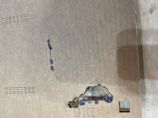
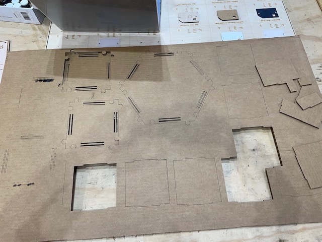 Initially, the test cut didn't go as planned, as it didn't cut all the way through. After adjusting the speed slightly, the second cut was successful. However, when I attempted to cut the entire piece, there was a fire in the machine, leading us to stop it. Despite changing the speed, it burned again during the second attempt. Ultimately, we decided to flip the cardboard over, and the cutting process went smoothly from there. Unfortunately, due to the time lost and material wasted, I couldn't produce as many pieces as I had hoped. Nonetheless, I learned a great deal from all the mistakes I made. My final oversight was that the cut of one shape overlapped another.
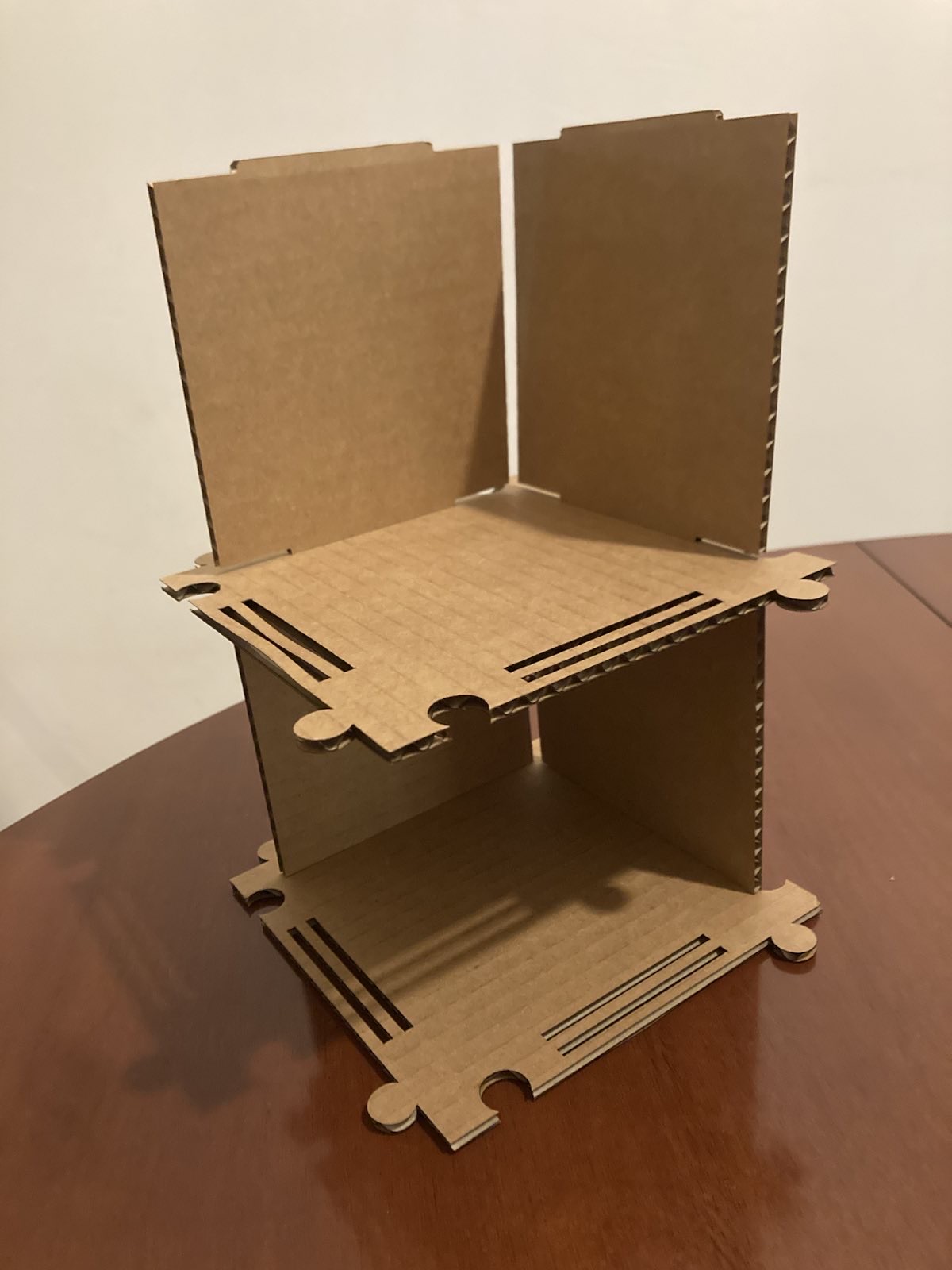
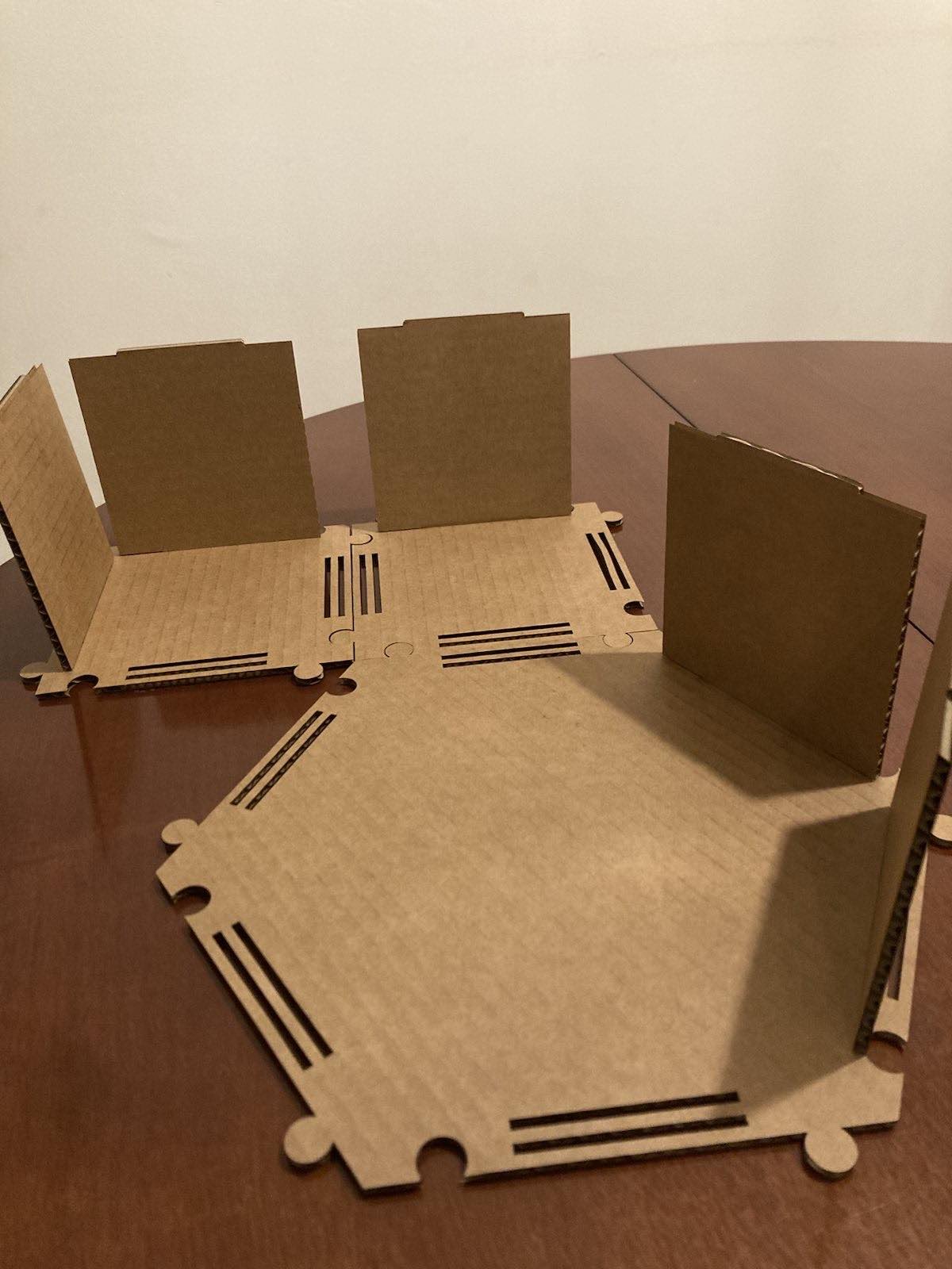
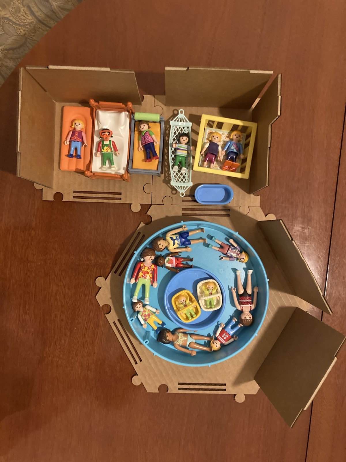
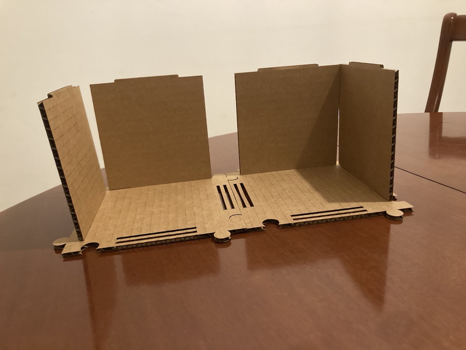 The dollhouse is designed in such a way that you can choose whether to place the pieces next to each other or stack them on top. In the end, my daughter filled it with her Playmobil toys and began playing with it.
Venyl Cutting
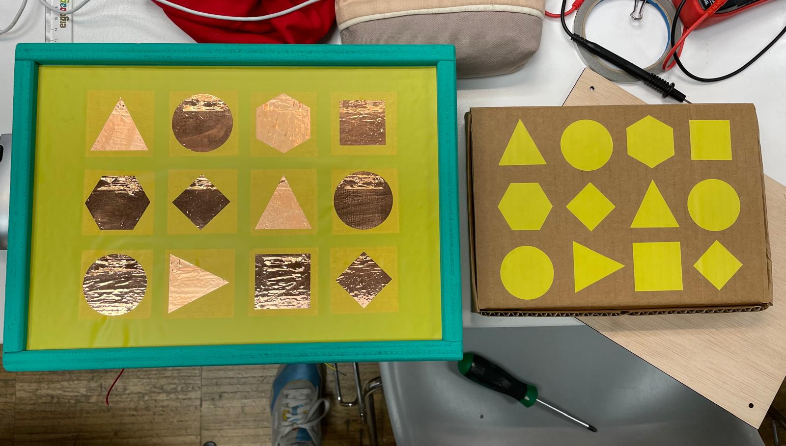 For my final project, I wanted to cut a sheet for the top of the box, and the cut-out elements could be used for the experiment kit.
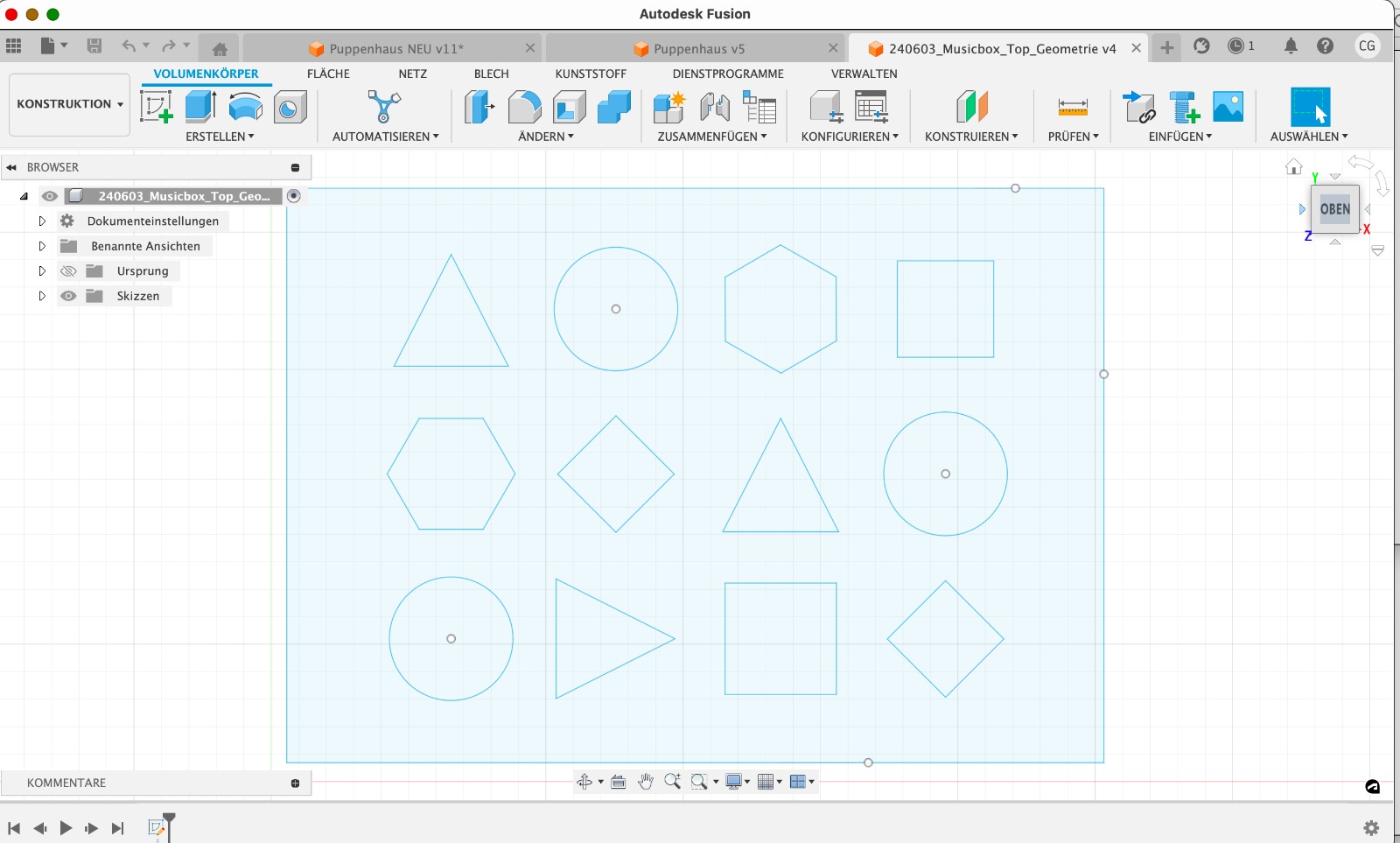
 I created a design in Fusion 360 for this. First, I measured the surface size of the box. Then, I drew a square that matched this size exactly. In a previous design, I had already determined where the 5 x 5 cm touch fields should be located. I was able to further develop this design. For this, I used two construction lines to mark the center of each 5 x 5 cm touch field. I then placed the center point to determine the centers of circles, squares, and polygons. Once I finished the design in Fusion, I exported it as a DXF file and then opened it in Rhino.
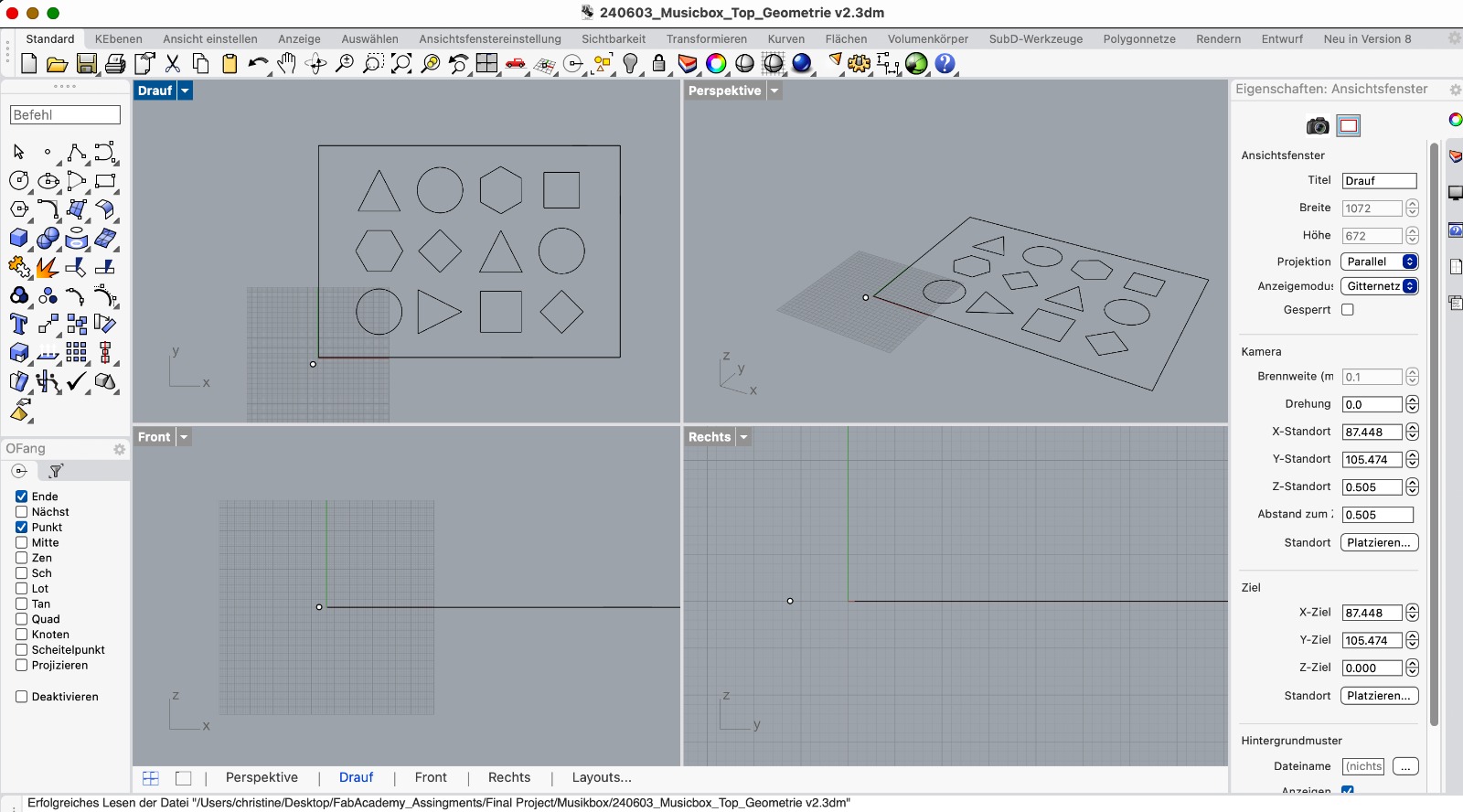 Next, I needed to use one of the lab computers. Here, I could open the design.
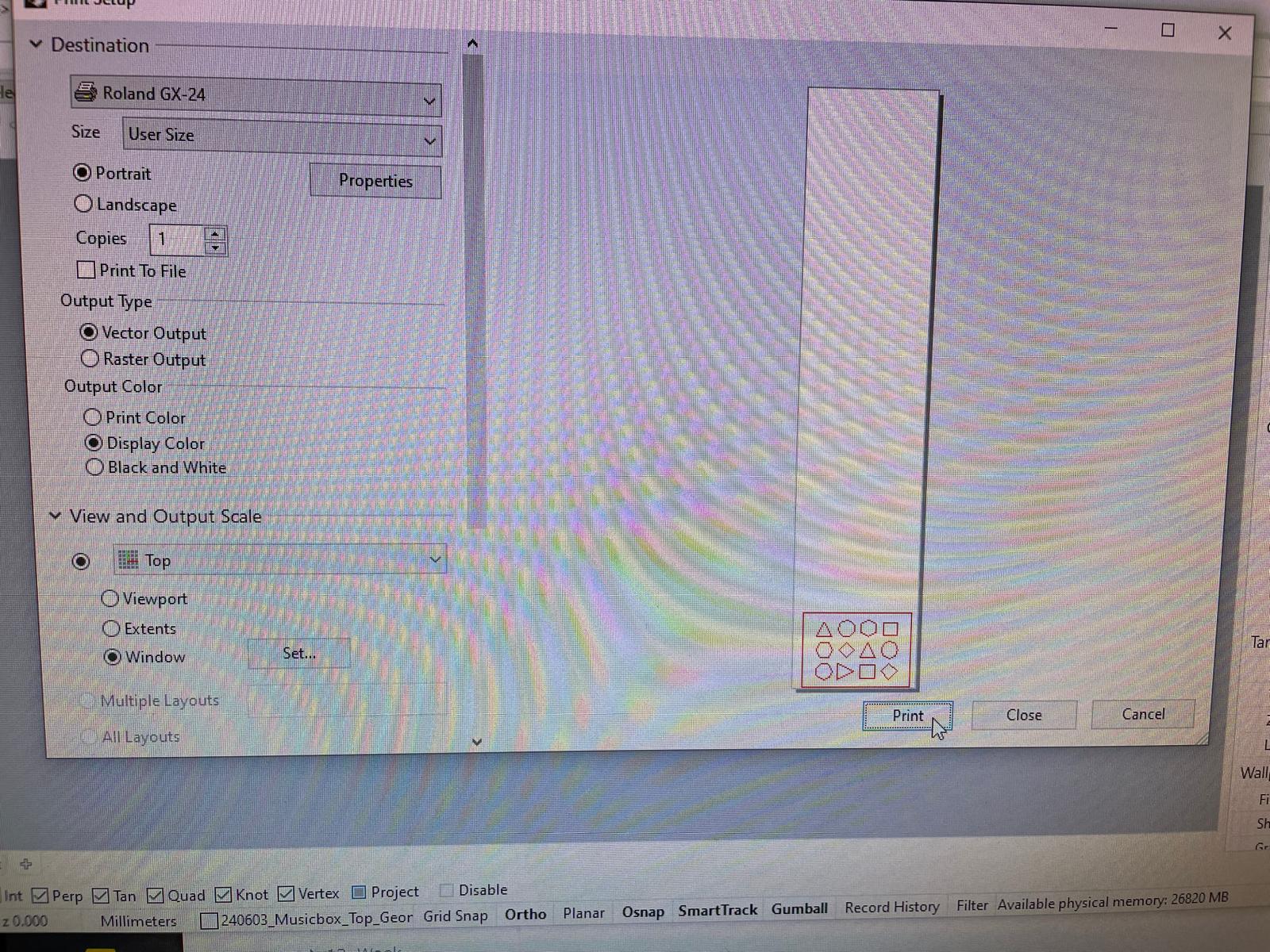 I also connected the vinyl cutter to the computer with a cable. The vinyl is fed into the machine from the back. It is possible to run a test first. During this test, the material should be cut through while the white protective film remains intact. To perform the test, simply press the Test button. I successfully completed the test. I could then use Rhino to issue the cutting command. A window opened. The vinyl cutter had already measured the size of the material itself. By selecting the option "Load from the machine," these measurements were transferred. Then, the print job could be initiated. Everything worked well.